1. Oil/Gas Field Surface Test and Metering Equipment Skid
Introduction
Oil/gas filed surface test and metering facility system is mainly used to measure yield, wellhead pressure, and physical property during temporary flow of production in the test process of flowing well in the initial stage of oil/gas field exploratory development so as to analyze oil reservoir.
High pressure mixture of oil, gas and water flows out from wellhead assembly firstly through choke manifold and throttle for depressurizing and then through high pressure throttle heater or heat exchanger, and then flows through angle type choke valve with the help of two-level heating coil for heating for further depressurizing and finally enters test separator.
Inside the test separator, the gas/liquid mixture is primarily separated into gas and fluid phases by means of energy consumption part at inlet. Gas goes into gas phase space, from which the liquid drop particle with the size of more than 100 ¦Ìm is separated at the rear space through the coalescence and rectification functions of stuffing, and then goes into mist eliminator to separate the liquid drop with the size of more than 10 μm. The natural gas with the liquid less than 0.05 g/Nm3 flows out of test separator via outlet. The natural gas is measured by senior orifice plate and three-pen Oil/Gas Field Surface Test and Metering Equipment Skid recorder. Separator pressure is controlled by pressure controller and pressure regulating valve and then the natural gas flows to flare system.
Liquid that enters liquid phase space flows pass washboard and the gas bulb with the size of more than 100μm is separated. The oil and gas mixture settles in the separation and settling chamber for a while. The separated crude flows over baffle board and into buffering chamber and then out of test separator through vortex breaker and oil outlet. The crude is measured by two parallel-connected positive displacement flowmeters or turbine flowmeters. Oil level is automatically controlled on site by liquid level controller and two liquid level regulating valves with parallel connection and then the crude flows into measuring tank.
Oily water flows out of test separator via drainage outlet and is measured by positive displacement flowmeter or turbine flowmeter on site. Interface between oil and water is automatically controlled on site by oil/water interface controller and interface controller and interface regulating valve, and then the oily water flows into cesspool.
Features:
- All the facilities are designed as skid-mounted unit and can be connected easily and reliably.
- All the equipment, apparatus, instruments can be moved and are applicable to harsh outdoor environment.
- All parts are manufactured and fitted together on skid. The framework is furnished with demountable protective shield.
- The whole test facility can be loaded on one moveable trailer, which is convenient for transport and helpful for handling and protection.
Oil/Gas Field Surface Test and Metering Equipment Skid
Technical Parameters:
- Oil/water measurement accuracy≤±1%
- Gas measurement accuracy ≤±5%
Media Physical Property and Processing Capacity
| Item | Unit | Value |
| Specific weight (d4 20) | 0.75-0.96 | |
| Viscosity (122 ˚F) | mPa·s | 0.45-2, 000 |
| Gas average molecular weight | Carbon unit | 17.64-23.3 |
| Operation temperature | ˚F | 41-176 |
| Operation pressure | Psi | 250/600/700/1, 440 |
| Maximum capacity (fluid) | BPD | 10, 000-17, 000 |
| Maximum capacity (gas) | MMSCFD | 6-100 |
| H2S | Yes |
2. Test Separator Skid (Three-phase or Two-phase)
Introduction
The test separator skid consists of test separator, control valves and relevant pressure/temperature/liquid level measurement instrument and data acquisition system. It is applied to separate oil/gas well production fluid into oil, gas and water and then to measure them.
Features
- Besides oil/gas/water high efficient separation function, the test separator is equipped with local pneumatic pressure and liquid level controller and pneumatic diaphragm control valves to test separator pressure and to automatically control oil level and oil/water interface level.
- Senior orifice plate with Burton recorder is adopted to measure natural gas flow rate. The skid can be applied to different oil wells by changing orifice plate with different bore sizes according to the actual flow on site without stopping production.
- Double circuit control and measurement are in parallel. Oil level control adopts two sets of diaphragm control valves. Sliding vane rotary flowmeter or turbine flowmeter is used for accuracy and control to solve the problem of uncertain flow rate.
- The natural gas separated from the separator is used as instrument air after filtering and drying. At the same time, the nozzle for compressed air is prepared to enhance the field adaptability of the separator.
- Double-safety valve and rupture disc are equipped to ensure safe operation. Test Separator Skid (Three-phase or Two-phase)
3. Measurement Calibration Skid
Introduction
The measurement calibration skid is applied to calibrate oil/water flowmeter of test separator and calculate correction coefficient.
When crude oil yield is so small that the flowmeter cannot measure flow rate, the fluid can be switched into measuring tank and the flow rate can be calculated by level gauge.
When the viscosity of crude is large, crude oil can be swerved to measuring tank and then is transferred by pump for load.
The measuring tank is double compartment normal atmosphere cuboid tank. Bypass manifolds are equipped at inlet and outlet. Steam heating coil is at the bottom. At the front of each compartment, there is level gauge, while at the rear part, there is manway for waste. Each compartment has one manway, flame arrestor on top. Outlets of the flame arrestors are connected to be one pipeline, which goes beyond safe area.
Specifications
- Standard cubage: 16 cubic meters
- Dimensions: 5.26 m×2.16 m×2.62 m
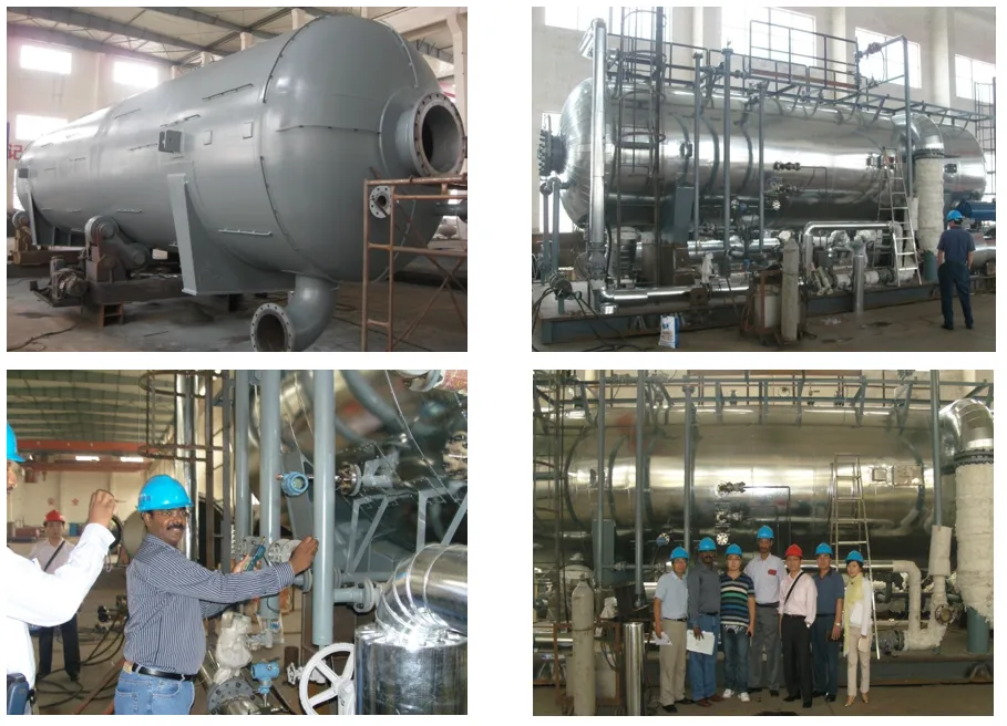
4. High Efficiency Specialized Separator for Oil/Gas Field
Light and medium oil high efficiency oil-gas-water three-phase separator
Introduction
The separator is mainly used to separate the oil-gas-water mixture produced from oil well into three phases: purified oil, associated gas and qualified sewage. It can be applied at the following sites:
onshore oil-gas field:
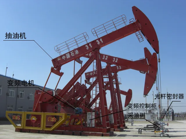
- Single well producing test field site
- Oil transfer station
- Joint station
offshore oil-gas field:
- wellhead platform
- CEP platform
- Land terminal
The mixture of oil, gas and water enters high efficiency three-phase separator gas-liquid separation area. The associated gas will be removed by gravity and collision separation. Oil-water mixture enters plate groove liquid distributor (patent component) from the clapboard bottom, then flows into separation chamber. In separation chamber, through two phase coalescence and rectifying stuffing, oil-water will remove the remaining water in the
oil and the oil in the sewage. The purified oil enters oil chamber, flows out of three-phase separator. The qualified sewage enters water chamber, flows out of three-phase separator. After removing liquid by mist eliminator, the associated gas from the separated chamber flows out of three-phase separator.
Features
- Applicable to deal with light, medium and heavy water-cut mixture of oil, gas and water
- Adopt anti-surf plate to inhibit the incoming fluid fluctuation influence to the rear area
- Assorted with chemical demulsifier with good performance
Features of three-phase separator
- Good separation effect
- Large dealing capacity
- High dehydration efficiency
- High automatic level
- Good adaptability
For crude oil with medium and high water cut, after once three-phase separator dehydration, the water cut in oil will be less than 0.3%, and the oil in sewage will be lower than 300 mg/L
Technical parameters
- Water content in outlet oil≤0.3%
Oil in outlet sewage≤300 mg/L
Liquid in outlet gas≤0.05 g/Nm3
Media Physical properties
| No. | Item | Unit | Qty |
| 1 | Specific gravity (d204) | 0.75-0.9162 | |
| 2 | Viscosity (50 ℃) | mPa·s | 1.5-85.0 |
| 3 | Condensation point | ℃ | 14-53 |
| 4 | Wax content | % | 10-43 |
| 5 | Asphalt content | % | 5.6-19.43 |
| 6 | Colloid content | % | 4.2-26.32 |
5. Medium and Heavy Oil High Efficiency Oil-Gas-Water-Sand Separator
Introduction
The separator is mainly used to separate the thick and extra thick oil-gas-water-sand mixture produced from oil well into four phases: qualified thick oil and extra thick oil, associated gas, qualified sewage and sand. It can be applied at single well producing test site, metering station, oil transfer station, joint station, CEP platform and land terminal.
Light and Medium Oil High Efficiency
oil-gas-water three-phase Separator
In the gas-liquid separation area, the incoming oil-gas-water-sand mixture separates the associated gas. The separated gas separates the liquid drop with diameter > 100μm across the second stage stuffing, then through the mist eliminator to remove the liquid, and flows out of the equipment from gas outlet. The separated gas-water -sand mixture from the gas-liquid separation area flows into tube type liquid distributor. After through the second stage coalescence stuffing and first rectifying separation stuffing to remove free water and part emulisifier and remove the oil in sewage, oil and water will separately flow into oil chamber and water chamber, then flow out of the equipment separately from oil outlet and water outlet. The separated sand from the oil and sewage water first flows through “V”± type stuffing, then through the sand collecting chamber to sand collecting component, through the internal pressure helping sand-drainage equipment to drain out of the equipment.
Features
- Adopt three patented technologies to realize the quick separation of thick oil, associated gas, water, sand and increase oil-gas-water-sand separation quality;
- Adopt dual-stage stuffing coalescence and rectifying technology to improve the oil-gas-water-sand separation condition and increase oil-gas-water-sand separation efficiency;
- Adopt coalescence and rectifying stuffing to improve the flow field condition of the dispersed water phase in the oil continuous phase and sand in the water continuous phase, realize the efficient and quick separation of dispersed and continuous phase;
- Adopt anti-surf plate to inhibit the incoming fluid fluctuation effects to the rear area;
- Adopt “inverse siphon” method to control oil-water interface and automatic instruments to control oil-water chamber liquid level and pressure to realize the automatic operation and eliminate the effects of human factors.
Medium Oil Technical Parameters
- Water content in outlet oil ≤0.5%
- Oil content in outlet sewage ≤300 mg/l
- Liquid content in outlet gas ≤ 0.05 g/Nm3
Heavy and Extra Heavy Oil Technical Parameters
- For thick oil, gas bubble diameter ≥150 μm
removal rate≥ 95% - Dehydration rate: 90%-98%
- Sand (particle size≥75μm) removing rate≥95%
- Liquid content of outlet gas: 0.01g/Nm3-0.05 g/Nm3
- Oil content of oily water: 500-1, 000 mg/L
- Water content of outlet oil: 5-15%
Media Physical properties
| Name | 50 ℃viscosity (mPa·s) | Specific weight (d204) | Gas oil ratio (Nm3/t) | Sand content (%) | Water content (%) |
| Medium oil | < 100 | 0.87-0.92 | 1-100 | 0.1-0.5 | 50-98 |
| Thick oil | 100-10,000 | 0.92-0.95 | 1-70 | 0.1-0.5 | 50-98 |
| Extra thick oil | 10, 000-50, 000 | 0.95-0.98 | 1-70 | 0.1-0.5 | 50-98 |
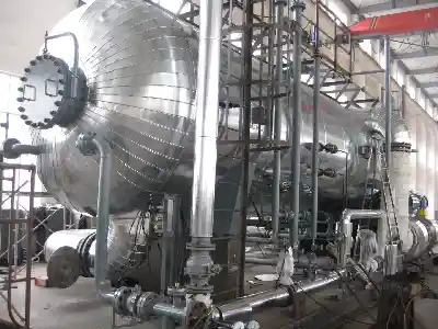
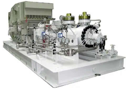
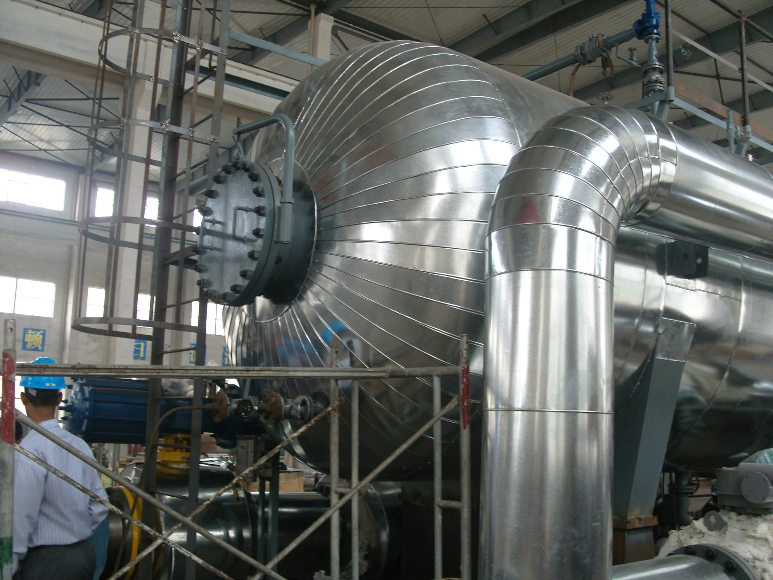
The picture below shows our customer’s custom-made separator undergoing painting process.
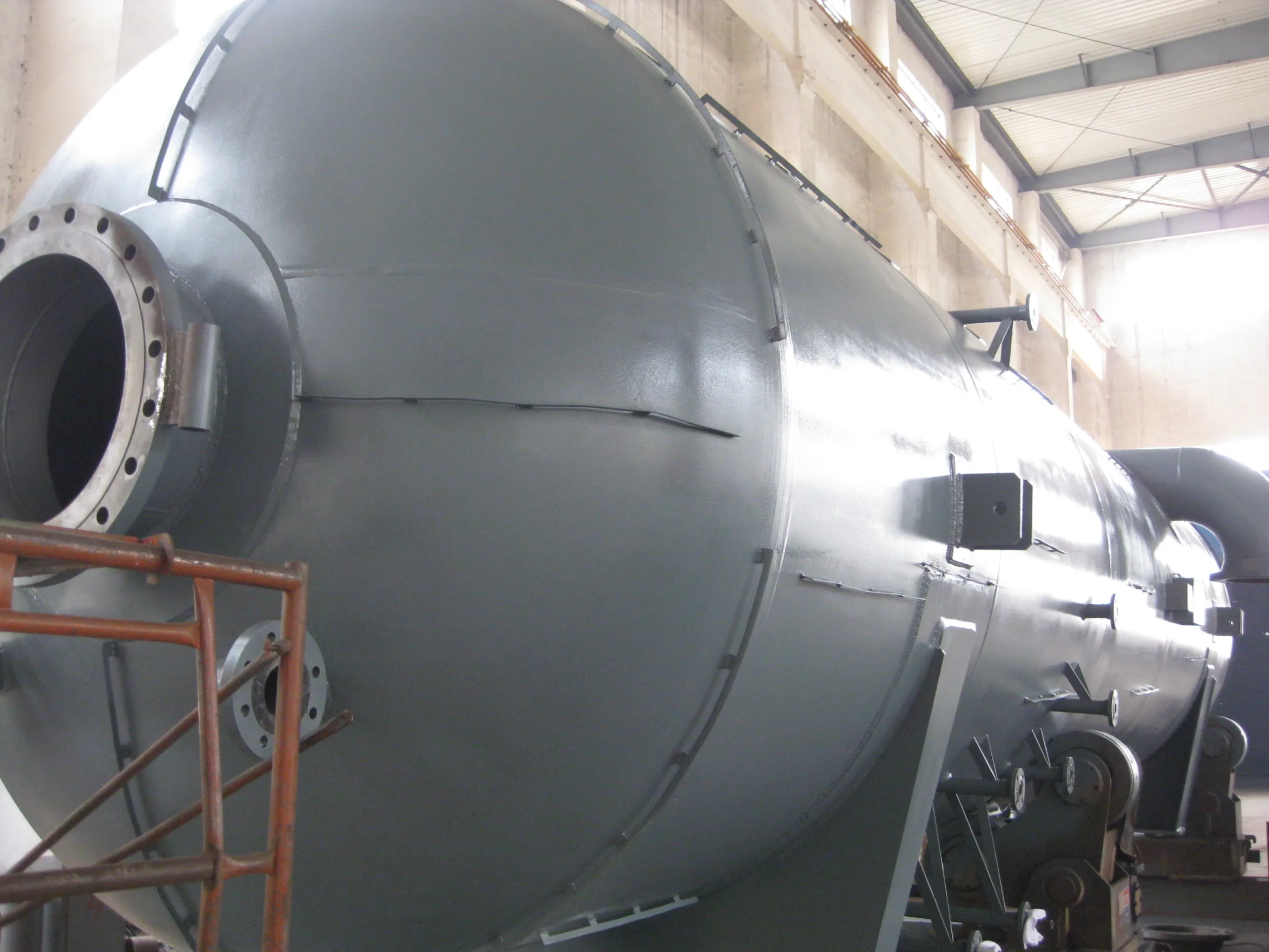
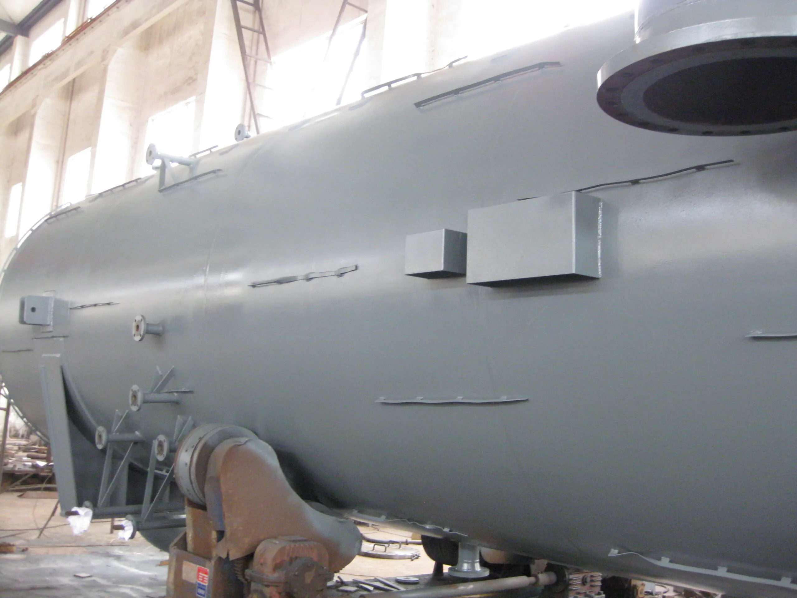
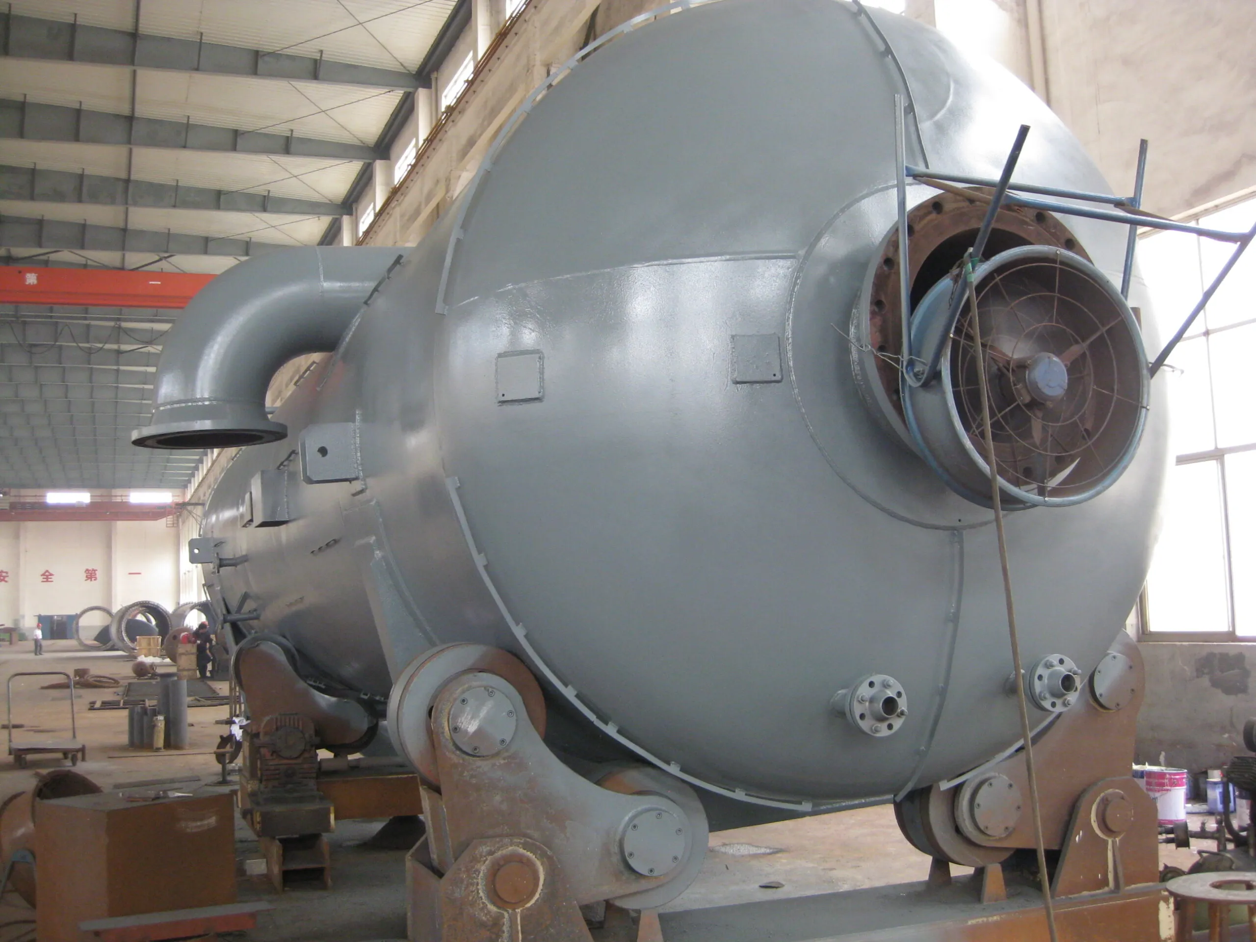
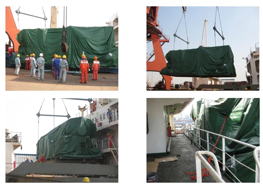
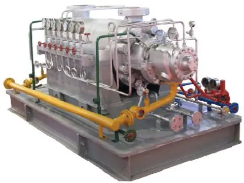
We Successfully Supply The Gas Separator for Sudan FULA oil field